Perlin noise is a classic procedural texture. It gives a wavy grayscale image, that has all sorts of uses in computer graphics. Commonly, it’s used to blend two textures together.

But what if you want to blend three or more textures together? Well today I have the answer.
As usual, you can jump straight to the code , or the demo at the end.
The problem
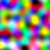
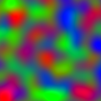
The first thing to cover is why doing the obvious doesn’t work. Suppose we made three different perlin noise images, one for each texture we want to blend. Then we interpret the height of each noise image as the strength of the texture in the blend. But we quickly end up with problems. The three noise images could all be high or low at the same time.

Above, I’ve put the three noise images together as red, green and blue channels of an image. The white and black areas are where all three colors coincide. When blending the textures, it’s necessary to scale these areas to a more normal range, or else they end up very bright / dark. Even after scaling, black is a problem as you end up scaling so much a small change in the input noise causes a huge change in the texture blend. As you can see, the output texture is a blurry mess.
The other obvious thing is to blend textures 1 and 2 with one perlin, then blend the result of that with texture three using a second perlin. That looks better, but that will be biased towards the third texture over the other two in a way that is hard to correct.
So what do we do?
Barycentric Coordinates
The trick is to use barycentric co-ordinates. Barycentric co-ordinates are where you specify a point in space according to its nearness to a fixed set of points, instead by measuring a long axes that are at right angles to each other.
Consider the classic RGB triangle:
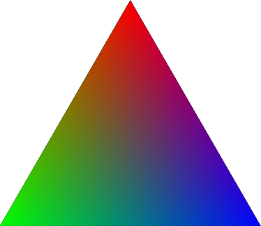
Any point inside this triangle could be described as, say, 10% red, 60% blue and 30% green. And given that description, I could easily find the point by taking a weighted average of the three corners with those percentages.
In this maner, we have a co-ordinate system descripting the area inside a triangle using three numbers that always sum to 100%. And we can describe the area outside the triangle, too, using negative numbers. The same idea works in multiple dimensions. In each case, \(n\) numbers summing to one are needed to describe a point in \(n – 1\) dimensional space.
Mathematically, barycentric co-ordinates are vectors \(\boldsymbol x\) where each component, \(\boldsymbol x_i\) is positive and the component sum \(\Sigma{\boldsymbol x_i}\) equals \(1\). I’ll return to this idea of component sum later.
The advantage of this co-ordinate system is it is explicitly based around blending. Position is defined by blending together the corners in the correct proportion.
Use in Perlin noise
I’m not going to describe how perlin noise works, that has been covered adequately in many places. But recall that a key part of the algorithm is that we randomly pick a gradient for each grid co-ordinate. Then we interpolate between those gradients to get the entire smooth image.
I’ve made two key changes. Firstly, I changed the algorithm to output a \(n\)-dimensional vector, not just a single value. This means replacing all additions in the algorithm with vector additons, and all the multiplications with scalar multiplications. Each output dimension is basically treated entirely separately. The only way the dimension are related is due to the second change. I’ve changed how the random gradients are generated.
Instead of generating \(n\) gradients at random, I generate a single \(n\)-dimensional barycentric gradient. A barycentric gradient is a \(n\)-dimensional vector with a component sum of zero. Because the components sum to zero, if I start at a barycentric point, and move in the direction of that gradient, I add a vector with component sum \(0\) to one with component sum \(1\). The result will also have component sum \(1\), so I’ll end up at a new barycentric point. The entire perlin noise algorithm is based off the gradient vectors, so this means it will only output barycentric points.
Generating random barycentric gradients
It’s actually super simple to generate random unit vectors with component sum of zero. We just generate random vectors with component sum zero, and repeat until we find one inside the unit sphere. Here’s some pseudo code:
  while True:
    x_1 = rand_between(-1, 1)
    x_2 = rand_between(-1, 1)
    x_3 = 1 - x_1 - x_2       #This ensures the component sum is zero
    x = Vector(x_1, x_2, x_3)
    if x.length < 1:
      return x.normalized()
Staying positive
In fact, if you just replace the gradient function as described, you end up with a noise function with \(n\) dimensions of output, with a range of \(-1\) to \(+1\) for each dimension, and the sum of all the components is zero. This isn't quite barycentric, but it'll still be useful, so I'm calling it "barycentric variant".
To get actual barycentric co-ordinates, we need the component sums to be one, and we need it to generate only values between \(0\) and \(+1\), as it is not a good idea to use negative values when blending. And we want the average value to be \(\boldsymbol c = (\frac{1}{n}, \frac{1}{n} ... \frac{1}{n})\), i.e. evenly spread between all the dimensions.
Perlin noise always takes value \(0\) at integer co-ordinates. So far, we haven't changed that. The trick of using barycentric gradients doesn't work unless we actually start at a barycentric co-ordinate. So we need to pick a starting value for the output on each integer co-ordinate, and blend between them at the same time as applying and blending the gradient. We could simply set the starting value to be the desired average value, \(\boldsymbol c\), but in the actual code , I'm a little smarter. Depending on the randomly chosen unit gradient for a given grid point, I pick a starting point that guarantees that we stay inside the triangle at all times.
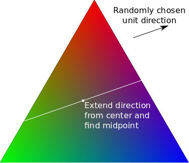
Suppose we've picked a random gradient \(\boldsymbol t\). First we calculate how far we can travel from \(\boldsymbol c\) in the selected direction while staying in the triangle. Say we can travel \(u\) units forward, and \(v\) units backwards. Then we output a starting value of \( \frac{u-v}{2} \boldsymbol t \) and a gradient of \( \frac{u+v}{2} \boldsymbol t \). Because normal perlin noise gives values in range \(-1\) to \(+1\), scaling and offsetting like this will give values between \(-v\) and \(+u\), ensuring we are always inside the triangle.
If also biases the output towards the corners of the triangle and away from the sides, so that, so each component will have an average value of \(\frac{1}{n}\), but will have an effective range of \(0\) to \(1\). This is exactly what we want for blending, and is true barycentric perlin noise.
Biomes
As an aside, another use for perlin noise with \(n\) dimensions is if you want to subdivide a map into \(n\) roughly equal size territories. Say you want to decide which places are desert, forest, grassland and so on. To do so, you can simply take the largest component of the n dimensional vector as the choice of biome. Barycentric perlin noise gives slightly nicer subdivisions than other ways or achieving this. Or you can take the best 2 components if you want transitional regions between the main regions.
I've included options for both in the demo below.
Results
Using RGB coloring, it's easy to visualize the differences.
The naive approach still has its uses, but as noted it generates white and black spots as the colors are chosen independently.
Using barycentric variant, we ensure that that we only pick colors from the RGB triangle, but the secondary colors, cyan, magenta and yellow, are equally prevalant to the primary colors.
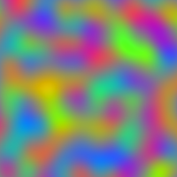
Finally done correctly, the algorithm picks spots of red, green and blue and smoothly blends between them - perfect for texture blending.
Demo
Here's a simple demo where you can experiment with using three independent perlin noises, versus using barycentric perlin noise. The output can dislayed in various ways. I threw in some cross hatching options as I liked the idea of using this noise for generating fake maps.
NB: The perlin noise output has been scaled up to give a more vivid demonstration. But that does lead to some clipping, noticably the black patches when using Independent Textures.
why not just use noise in the hue channel
Aside from the fact that would only work for three channels, not more, hue is a cyclic value, while perlin outputs a range. So it’s be impossible to see a blend across the whole range of reds, and some colors would be more frequent than others.